Wenzhou AIOU Optical Communication Co., Ltd.
Leave Your Message
0%

An Optical Sfp Module is a compact, pluggable transceiver used in switches, routers, and other network equipment. It converts electrical signals into optical signals for transmission through fiber. At the receiving end, it converts light back into electrical data. The module usually fits into an SFP cage and connects through an LC fiber connector.

Small device. Big responsibility.

Inside, a transmitter uses a laser or LED, while a photodiode receives incoming light. Common wavelengths include 850 nanometers for short-range multimode fiber and 1310 or 1550 nanometers for longer links. The module also stores identification data, operating limits, and diagnostic information in electronic memory. Network administrators can often monitor temperature, voltage, optical power, and laser bias through digital diagnostics.

In practice, selecting an Optical Sfp Module requires more than matching connector types. Engineers must check transmission speed, fiber type, wavelength, reach, temperature rating, and equipment compatibility. A 10-kilometer module may perform poorly on an unsuitable fiber path. That detail is easy to overlook. Real installations are messier.

This guide explains how the module’s transmitter, receiver, and monitoring functions work together. It also considers practical installation concerns, including link budgets, insertion loss, and optical cleanliness. Manufacturer specifications provide the foundation, but field testing remains valuable. Some labels appear clear until different vendors use similar terms differently. Careful verification prevents expensive troubleshooting and unstable links.

What Is an Optical SFP Module and How Does It Work?

Optical SFP Module: Definition and Core Purpose

What Is an Optical SFP Module and How Does It Work?

Optical SFP Module: Definition and Core Purpose

An Sfp Optical Module is a compact, pluggable transceiver for network equipment. It converts electrical signals into optical signals and reverses that process at the receiving end. The module fits into a compatible port on a switch, router, or other communication device. Its core purpose is simple: extend data connections through fiber cables while supporting stable, high-speed transmission.

Inside, a transmitter uses a light source to send data through the fiber. A receiver detects incoming light and changes it back into electrical information. Technicians must match the module with the fiber type, transmission distance, connector, and required data rate. In field installations, a mismatch can cause weak signals, packet loss, or no link at all. I have seen labels checked twice, yet the cable type was overlooked. Small details matter.

Tips: Check the equipment manual before installation. Keep protective caps on unused ports. Clean fiber connectors with approved tools, not ordinary cloth. Confirm the wavelength and distance rating before connecting cables. A link may appear active but still perform poorly when optical power is marginal. Testing with a calibrated meter is wiser than trusting indicator lights alone. Oversights happen, even during routine work.

Main Components Inside an Optical SFP Module

What Is an Optical SFP Module and How Does It Work?

An optical SFP module is a compact transceiver that converts electrical signals into light and back again. Its main parts are arranged inside a small metal housing. The transmitter optical subassembly, or TOSA, contains a laser diode, driver circuit, and alignment elements. The laser sends data through a fiber at a selected wavelength. A 10g Sfp Optical Module may use a finely controlled laser for high-speed transmission across data centers or campus networks.

The receiver optical subassembly, called ROSA, includes a photodiode and an amplifier. The photodiode detects faint light pulses and changes them into electrical signals. A limiting amplifier then reshapes those signals for the host device. Inside the module, a controller stores identification data in memory and monitors temperature, voltage, and laser bias. These readings help technicians locate unstable links before failure becomes obvious.

Not every fault is obvious.

The electrical connector links the module with the switch or router. The optical port uses a precision sleeve to hold the fiber in position. Even a small alignment error can increase insertion loss. A protective cage also supports grounding, cooling, and mechanical stability. During practical testing, engineers check optical power, receiver sensitivity, temperature, and error rates. The design is precise, but not flawless. Dust, heat, or repeated insertion can still affect performance, so clean handling deserves more attention than it usually receives.

How an Optical SFP Module Transmits Data

What Is an Optical SFP Module and How Does It Work?

An optical SFP module is a compact, hot-swappable transceiver used in network equipment. It converts electrical data into optical signals for fiber transmission. Inside, a laser diode creates rapid light pulses that represent digital bits. The light carries the data. At the receiving end, a photodiode detects these pulses and changes them back into electrical signals. Signal-processing circuits then reshape the data before sending it to the switch or router.

When a switch transmits data, its electrical interface drives the SFP transmitter. The module sends light through a fiber core at a specified wavelength and speed. Duplex fiber usually uses separate strands for sending and receiving. Distance depends on the optical power budget, fiber type, and connector quality. In field installations, I check the wavelength, fiber mode, polarity, and connector condition before testing performance. A tiny dust particle can create surprising loss.

Transmission is not always perfect. Small losses accumulate. Tight bends, poor splices, or incompatible modules may increase attenuation and errors. An optical link can remain active while its error rate quietly rises. I have sometimes blamed the transceiver first, only to find a contaminated patch cord. That mistake is worth remembering. Datasheet values describe controlled conditions, not every rack or cable route. Technicians should measure received power, inspect alarms, and leave practical margin for heat, aging, and installation variation.

How the Module Receives and Converts Optical Signals

An optical SFP module receives data as pulses of light through a fiber connector. Inside, a photodiode detects these pulses and creates a tiny electrical current. The transimpedance amplifier strengthens that current. A limiting amplifier then reshapes it into a stable digital signal for the network device.

The process is sensitive. Very sensitive.

A clock and data recovery circuit may retime the signal before delivery to the host. This helps reduce jitter, although it cannot repair every transmission error. The module also reports temperature, voltage, and optical power through a digital monitoring interface. These readings help technicians identify weak signals before a link fails.

On the network side, demand keeps rising. The International Telecommunication Union’s Facts and Figures 2023 reported 5.4 billion people online, representing about 67% of the global population. More connected users mean more traffic across access and data-center networks. A 2024 optical-network market forecast also identified higher-speed connections as a major growth driver.

In field work, the optical path is rarely perfect. Dust on a connector, a sharp fiber bend, or excessive insertion loss can reduce received power. The module may still show a link, but performance can remain unstable. That is the part many simple diagrams miss. Technicians should inspect connectors, check power levels, and compare readings with the applicable IEEE 802.3 limits. Measurements matter more than assumptions.

Key Optical SFP Module Types and Specifications

An optical SFP module is a compact, hot-swappable transceiver used in network switches, routers, and storage equipment. It converts electrical signals into light and sends data through fiber. At the receiving end, it changes light back into electrical signals. In a real installation, the module is only one part of the link. Fiber type, connector cleanliness, and switch compatibility matter just as much.

Common types include multimode SX modules for short links and single-mode LX or ZX modules for longer distances. BiDi modules use different transmit and receive wavelengths over one fiber strand. WDM versions separate traffic by wavelength, helping one fiber carry multiple signals. The phrase Sfp Optical Module Wdm often refers to this wavelength-based design. Check whether the module uses CWDM or DWDM, because their channel spacing and deployment costs differ.

Key specifications include data rate, operating wavelength, transmission distance, fiber mode, connector type, and temperature range. A 10-kilometer rating may assume low-loss fiber and clean connections. It is not a guarantee in every building. Digital diagnostics can report temperature, voltage, and optical power, which helps technicians find weak links before failure. Still, monitoring values can drift, and I would not treat one reading as absolute proof. Confirm it with link counters, a power meter, and the physical cable path.

Compatibility, Installation, and Operating Considerations

An optical SFP module converts electrical network signals into light through a fiber link. Its compatibility depends on more than physical size. Check the port speed, transmission distance, wavelength, fiber type, and connector before installation. The host device may also require coded module support. A module can fit perfectly and still fail.

For a Sfp Fiber Optical Module Bidi, use the correct matching pair. One side transmits at one wavelength, while the other receives it. Confirm the Tx and Rx wavelength labels carefully.

During installation, power down the device when required, remove the protective caps, and avoid touching the optical ends. Clean connectors with approved lint-free tools. Tiny dust particles can weaken the signal. Keep the fiber bend radius gentle.

Operating conditions deserve equal attention. Check temperature limits, ventilation, optical power, and diagnostic readings. A link may work in a cool test room but become unstable inside a crowded cabinet. I have seen loose latches and sharply bent fibers create intermittent faults. The module was not defective. The installation was rushed. That distinction matters. Leave unused ports capped, secure the cable, and record signal levels after commissioning. Recheck them when errors appear. My own process is not perfect; I sometimes rely too heavily on initial readings. Long-term monitoring provides better evidence.

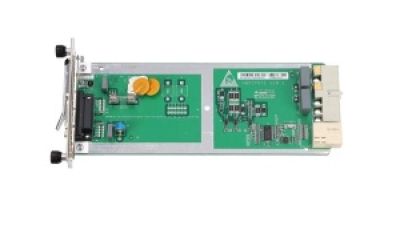
PRTE OLT Service Board: Building Reliable GPON/EPON FTTH Access Networks

A high-performance OLT service board is a key component for building reliable GPON and EPON FTTH access networks. Designed for optical line terminal systems, it supports stable communication between the core network and distributed optical network units, enabling service providers to deliver broadband, voice, video, and other IP-based services through fiber infrastructure. Its optical interface is engineered for consistent transmission quality, helping maintain dependable connectivity across different access environments.

With efficient data processing and stable optical performance, the service board can support high-speed broadband access for homes, offices, campuses, and community networks. It helps simplify network deployment by integrating essential optical access functions into the OLT platform, while supporting flexible fiber distribution and efficient bandwidth management. Compatibility with both GPON and EPON architectures allows operators to select an access technology according to coverage requirements, subscriber density, and existing infrastructure.

Built for continuous operation, the board contributes to improved network availability and easier maintenance. Its dependable design can help reduce service interruptions, support scalable subscriber growth, and provide a practical foundation for expanding FTTH coverage. Through stable optical transmission and efficient access control, it enables telecom operators and internet service providers to develop fast, resilient, and manageable fiber access networks.

FAQS

What is an optical SFP module?

It is a compact transceiver for network equipment. It converts electrical data into light and back again. The module can be replaced while equipment remains powered. Small housing, complex work.

What does the transmitter optical subassembly do?

The transmitter optical subassembly contains a laser diode, driver circuit, and alignment parts. The laser creates rapid light pulses. These pulses carry digital data through fiber at a selected wavelength.

How does the receiver optical subassembly work?

The receiver optical subassembly uses a photodiode to detect faint light pulses. An amplifier converts and reshapes them into electrical signals. The network device can then process the recovered data.

How does data travel through an optical link?

A switch sends electrical data into the module. The module sends light through the fiber core. At the other end, another module changes the light back into electrical data. Duplex fiber usually uses separate strands for sending and receiving.

What determines the transmission distance?

Distance depends on optical power, fiber type, wavelength, and connector quality. Tight bends and poor splices reduce the available margin. A tiny dust particle can create surprising loss.

Why can errors increase while the link still works?

Small losses may accumulate without immediately stopping the connection. Heat, aging, contamination, or misalignment can increase attenuation. The link may appear active while errors quietly rise. Not every fault is obvious.

What information does the internal controller monitor?

The controller stores identification information in memory. It also monitors temperature, voltage, and laser bias. These readings help technicians find unstable links earlier. Measurements can still miss some problems.

How should technicians test and maintain an optical module?

They should check wavelength, fiber mode, polarity, and connector condition. Testing should include optical power, receiver sensitivity, temperature, and error rates. Clean connectors and avoid sharp fiber bends. I have sometimes blamed the module first, which is not always fair.

Conclusion

An Optical Sfp Module is a compact, replaceable transceiver used in networking equipment to connect electrical data systems with optical fiber links. It typically contains a transmitter, receiver, optical interface, control circuitry, and a protective housing. When transmitting data, the module converts electrical signals into pulses of light through a light-emitting device or laser, then sends them through a fiber at a defined wavelength and speed. This process enables reliable communication over distances that copper cables may not support.

On the receiving side, a photodetector captures incoming light and converts it back into electrical signals for the network device to process. Optical SFP modules are available in different versions based on transmission speed, fiber type, wavelength, connector design, and operating distance. Proper compatibility is essential, including matching the module with the equipment, fiber, data rate, and link requirements. During installation, users should handle fiber connectors carefully, observe optical safety practices, and maintain suitable temperature, power, and cleanliness conditions for stable operation.


Clara

Clara

Clara is a dedicated marketing professional at a leading high-tech enterprise established in 2006, specializing in optical network access solutions. With a profound understanding of the company's diverse product offerings, she plays a pivotal role in enhancing the visibility of their cutting-edge......
Previous Best Fiber Transceiver Manufacturers in China